Oculus Rift CV1 Teardown
During quarantine, I came into possession of a used Oculus Rift CV1 setup (that’s the original one) that had an infuriating tendency to disconnect if you moved your head around too fast. After some basic debugging techniques (ahem, turning it off and on again), I determined that there was a hardware issue in the headset and, since the CV1 has been discontinued for some time, I would have to fix it myself.
I was disappointed to find that there were no good teardown guides for repairing the CV1. iFixit’s guide was light on details you’d want for taking apart your own CV1. The best content I could find was a series of unedited (and, therefore, lengthy) YouTube videos that ended up only being useful for the first couple steps.1
Fast forward through two more pre-broken headsets from eBay and a handful of individually-purchased components, some of which I personally broke and some of which were sold as working but weren’t, and I’ve gotten pretty good at disassembling and reassembling CV1s. Unfortunately, I only ended up with the equivalent of my first headset (complete with hardware flaw) and one other frankensteined, but functioning, headset, so I wouldn’t say it was worth the money. But at least it was a fun quarantine project, and I hope someone finds this guide useful if they need to do their own CV1 surgery!
What You’ll Need
- T4 Torx screwdriver
- #0 Phillips head screwdriver with a narrow shaft 3” or longer
- medium-large flathead screwdriver or spudger
- small flathead screwdriver, ~1/16” wide
The Phillips head will have to fit in a very narrow space, so most replaceable-bit screwdrivers with a bulky socket for the bits won’t fit. Also, the screws are quite small, so a magnetic screwdriver and/or an organizing tray will help keep you from losing them.
Parts List
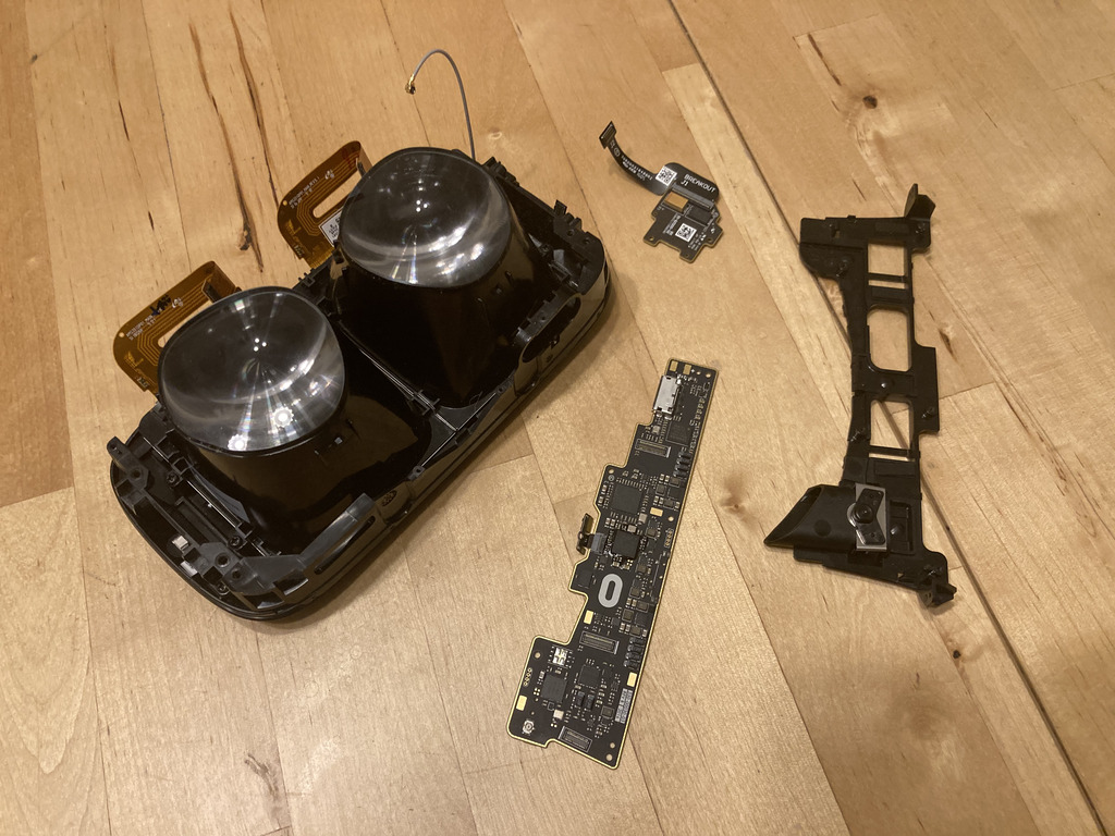
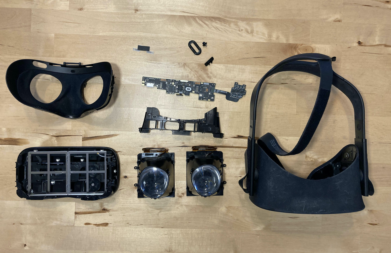
Ignoring the parts that can be removed without any tools, these are the parts you will end up with at the end of this teardown.
- 1x head strap/outer housing assembly
- 1x fabric face shroud
- 2x lens assemblies
- 1x moveable lens mount/front housing
- 3x PCB
- 1x main board
- 1x breakout board
- 1x proximity sensor board
- 1x main board support
- 1x ribbon cable brace
- 1x IPD slider assembly
- 1x outer ring
- 1x slider thumb
- 2x springs
- 1x rack gear/thumb holder
- 19x T4 Torx screws
- 9x small Phillips head screws
- 4x large Phillips head screws
- 1x Phillips shoulder screw
Step-by-step Teardown
The next several sections are separated somewhat arbitrarily into sets of steps that felt like useful checkpoints. I suggest you skim each section before following the steps, just to get a feel for what you’re about to do and to maybe help set up your light/tools/workspace for best effect.
I’ve torn down headsets half a dozen times following these instructions, but keep in mind that I am not an expert and if you aren’t careful you may damage your headset. Follow these instructions at your own risk; I am not responsible for any damage you may incur by following them. With that disclaimer out of the way, let’s get started!
1. Preliminaries
Before getting into the teardown proper, start by removing all the extranous parts: headphones, foam faceplate and cable. I also recommend you unvelcro the top strap and wrap it around the brace for the back of the head to keep it out of the way.
2. Face Shroud
Removing the flexible fabric shroud is, right out the gate, one of the more stressful parts of the process, because you’re doing it almost totally blind and it requires a good amount of prying that makes you feel like you’re about to break the headset. The fabric is held in shape by an outer plastic frame, which is screwed into the outer housing of the headset.
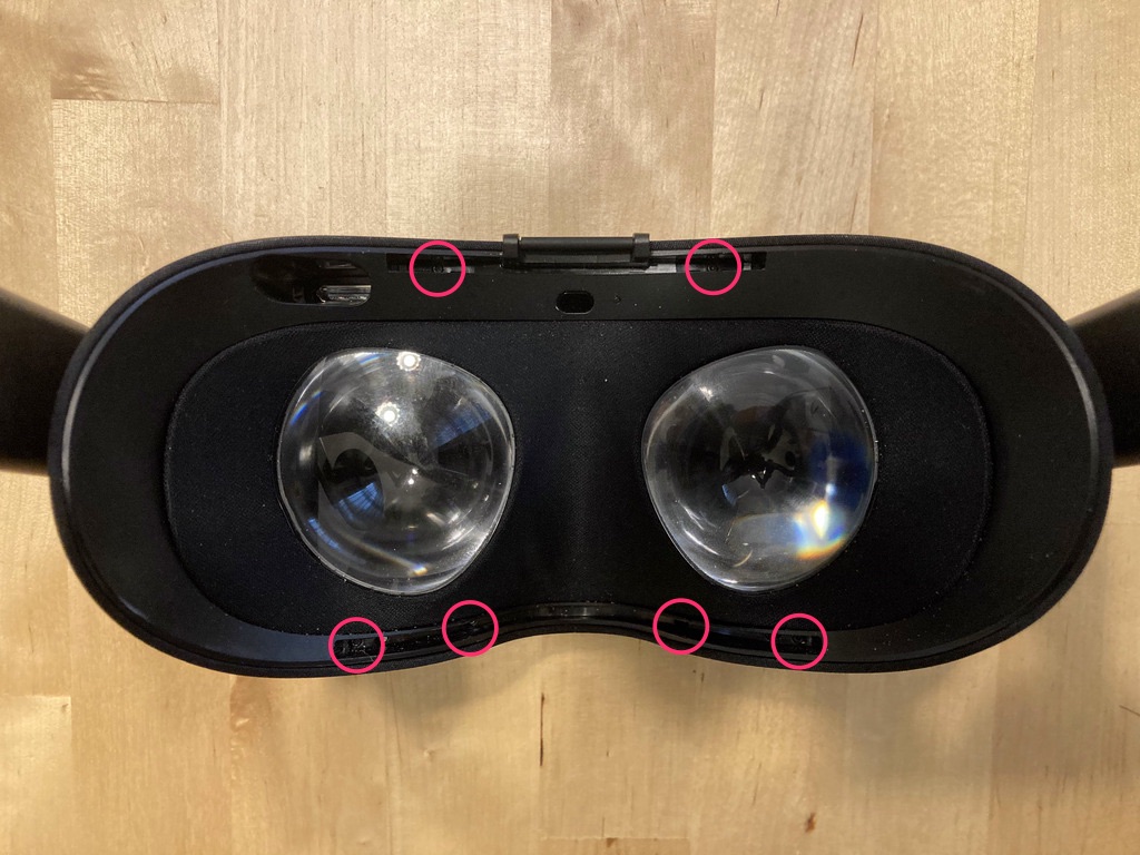
First, remove the 6x T4 screws.
Next, you have to separate the tabs that keep the left and right sides of the plastic frame attached to the outer housing.
Insert your screwdriver between the plastic frame and the outer housing, without going too deep, and slide it along until it’s at the far left (or far right) side of the headset. If you can pull the plastic frame ~1/4” away from the outer housing, you know you’ve separated the tabs. You can let the now-separated frame rest back against the outer housing; it doesn’t tend to re-engage unless you push it.
Watch Your Screwdriver
Keep your screwdriver head tilted away from the inside surface of the outer housing. Some infrared LEDs are adhered there and you don't want to disturb them.
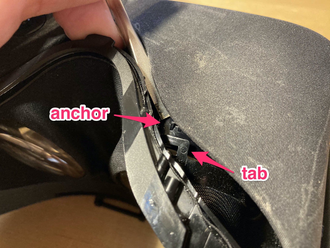
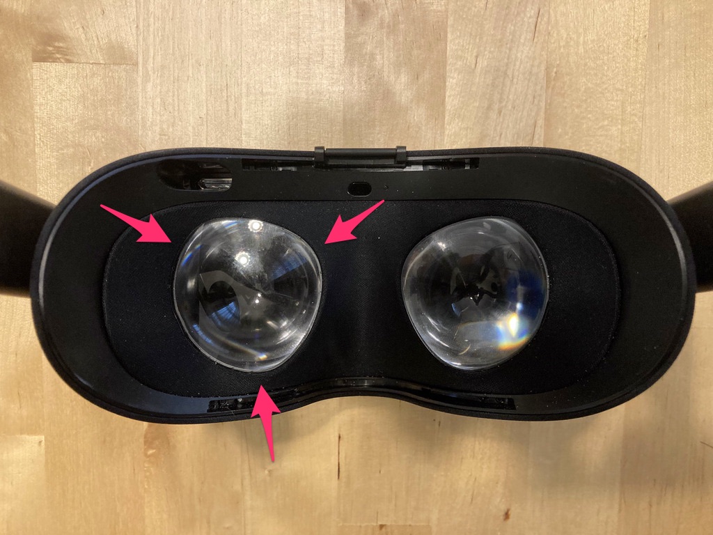
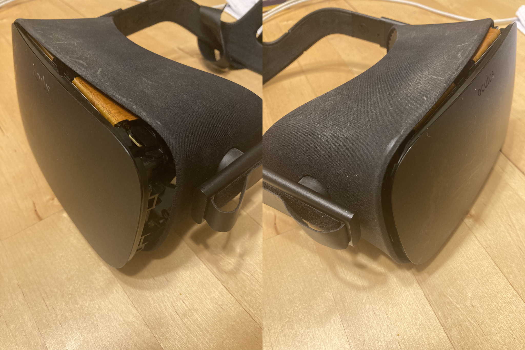
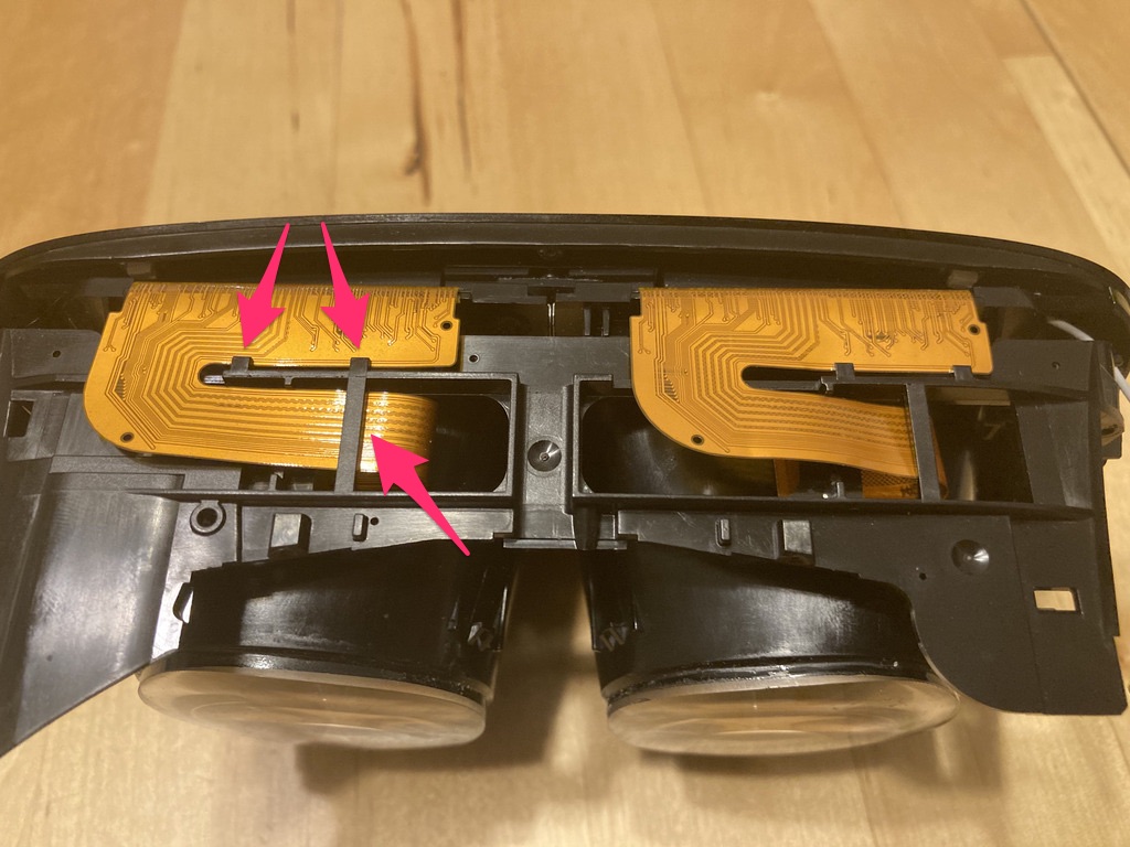
Next, you have to separate the fabric shroud from the lenses. Each eye hole in the shroud has a floating plastic ring attached to the fabric with three tabs that clip onto anchors on the lens housing. This picture is a view from the inside so you can see what you’ll be blindly working with.
This step is probably the one that most makes you feel like you’re going to break the headset. It’s also a pain to get a light into the right place to see what you’re doing. It’s the best technique I’ve found to do this, however.
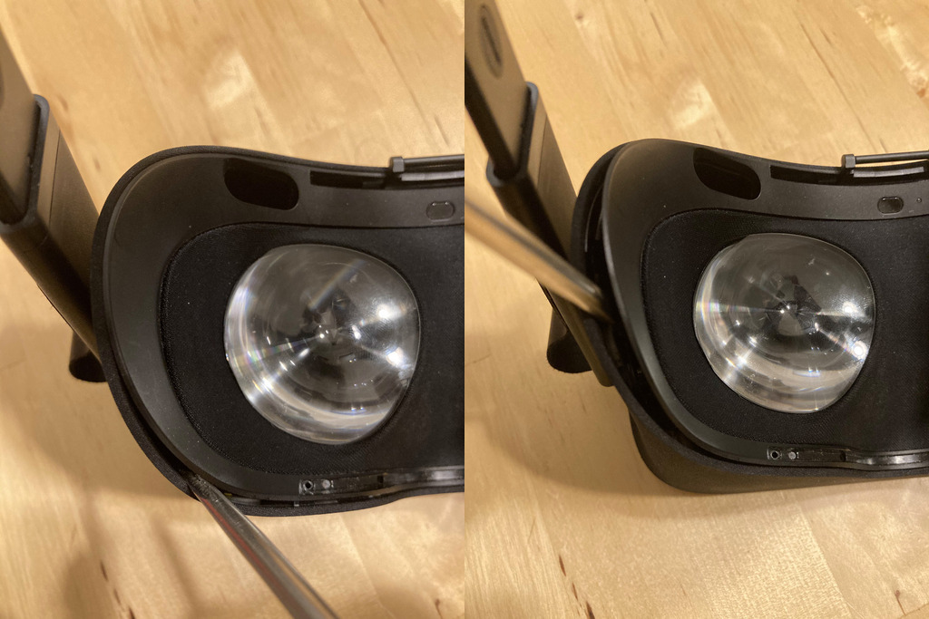
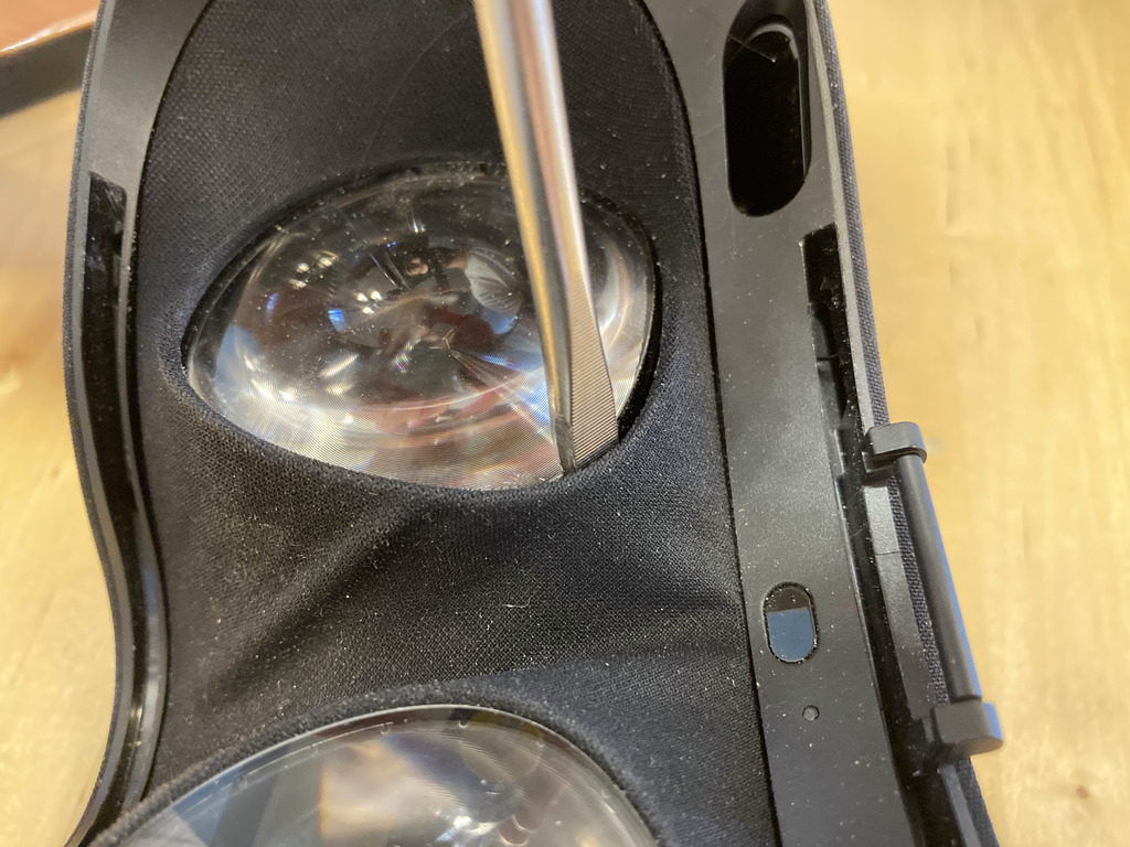
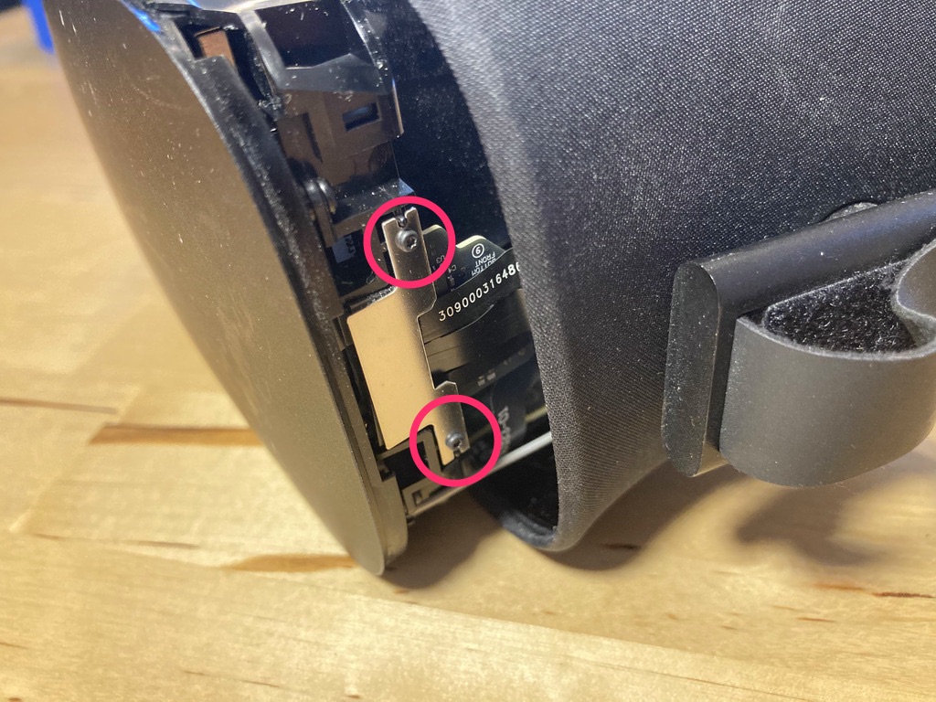
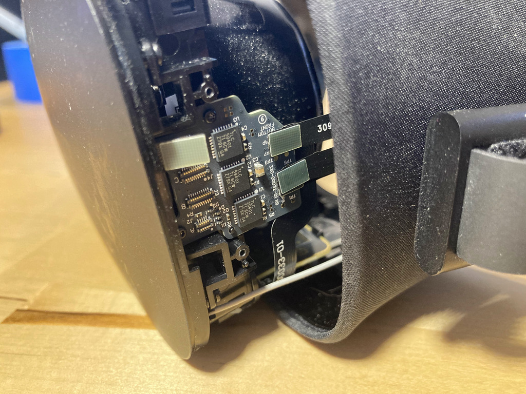
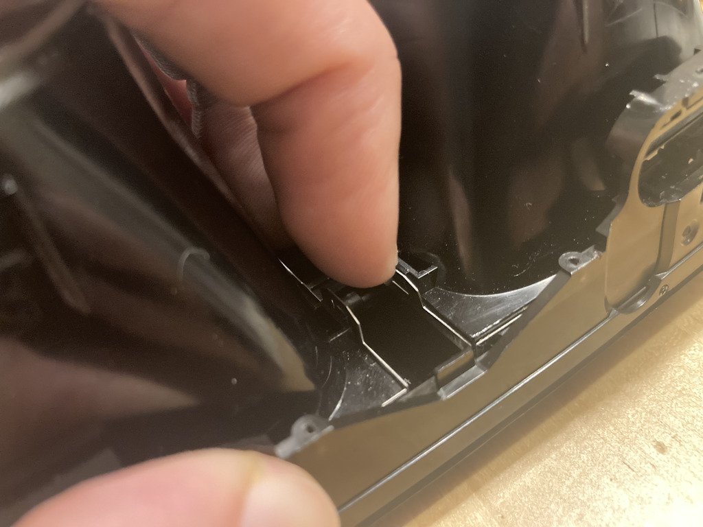
The tab on the bottom side of the lens can be reached with the flathead screwdriver if you gently pull the shroud’s plastic frame away from the outer housing of the headset. Photographing the moment of release is difficult, so here’s what it looks like right after the tab has been separated. Note that the screwdriver is held at a shallow angle so it can get under the tab.
Once you’ve separated the first tab, you’ll gain some flexibility to move the plastic ring up a little bit, which will help with the next two tabs. Here’s a reference for where all three of the left lens tabs can be found. (The tab locations are mirrored for the left and right lenses.)
Lightly tug on the ring to pull it away from the lens, and slot the screwdriver in the gap. Slide the screwdriver around the ring, which should pop off the remaining two tabs with not much effort.
After you’ve done one lens, you should be able to tug most of the shroud out at least 1/2”. That will make it easier to maneuver your hands and screwdriver in order to repeat these steps for the other lens.
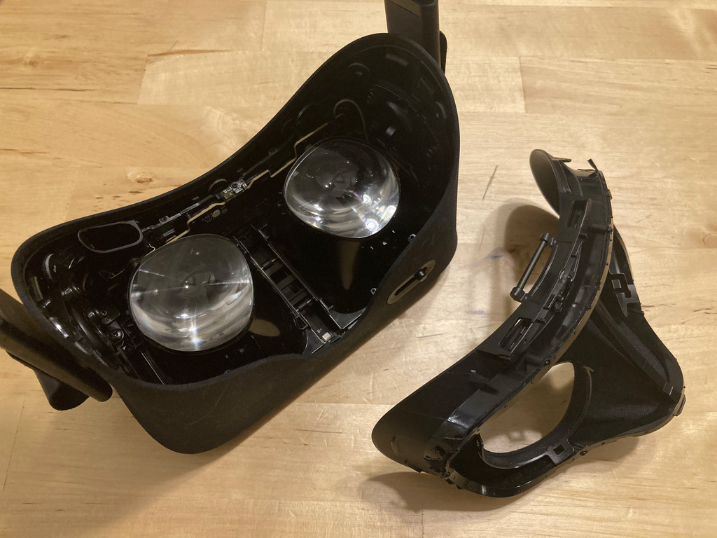
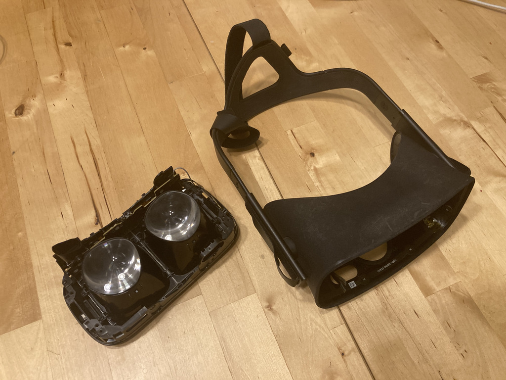
When you’ve got them apart, your headset should look like this!
3. IPD Slider
Before removing the outer housing, the IPD slider on the bottom right has to be taken out. It’s held in by 1x T4 screw, so remove that first.
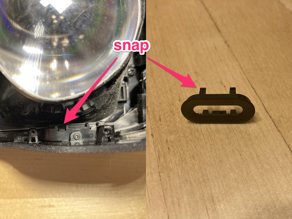
Next, release the front two plastic snaps holding the outer ring using the small flathead screwdriver by pressing them in and down.
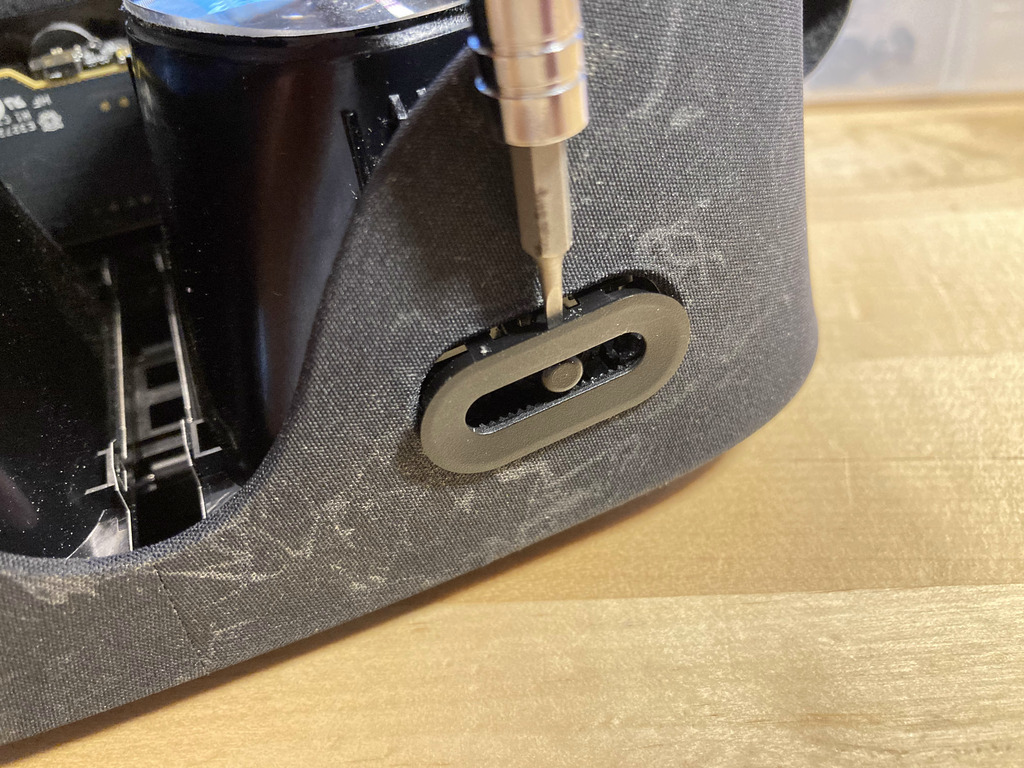
Once you’ve pushed the snaps in, the outer ring has probably mostly separated itself from the headset. If it hasn’t, use your screwdriver to lever the ring away from the housing. It’s held in by inaccessible snaps on the inside and back of the slider assembly, so you’re trying to tilt it until those snaps simply pull away from their anchors.
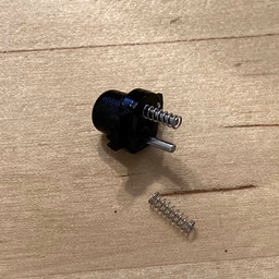
Don't Lose the Springs
Underneath the switch's thumb there are two tiny springs. Make sure you work slowly and/or in an enclosed space to prevent them flying off into the distance.
At this point, the slider thumb and springs have probably launched themselves at you, so put them aside.
A note on reassembly: the slider thumb is asymmmetrical and only goes in one way.
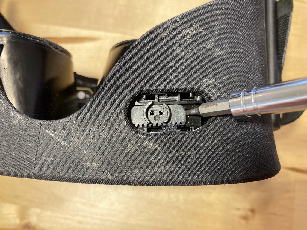
Lastly, pop out the rack gear with a flathead screwdriver or your fingers.
Another note on reassembly: make sure you place the rack gear so you get the full range of the slider.
4. Outer Housing
The outer housing is attached to the front of the headset by a bunch of screws of all sizes.
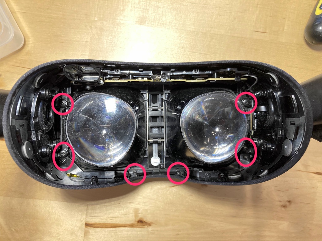
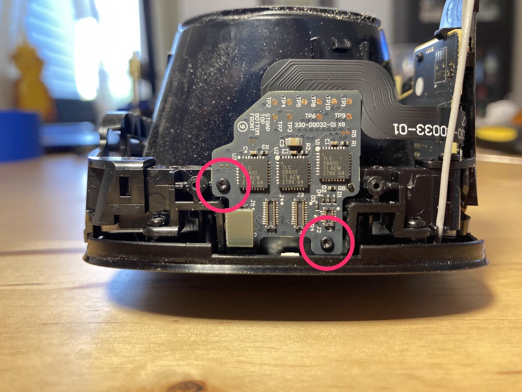
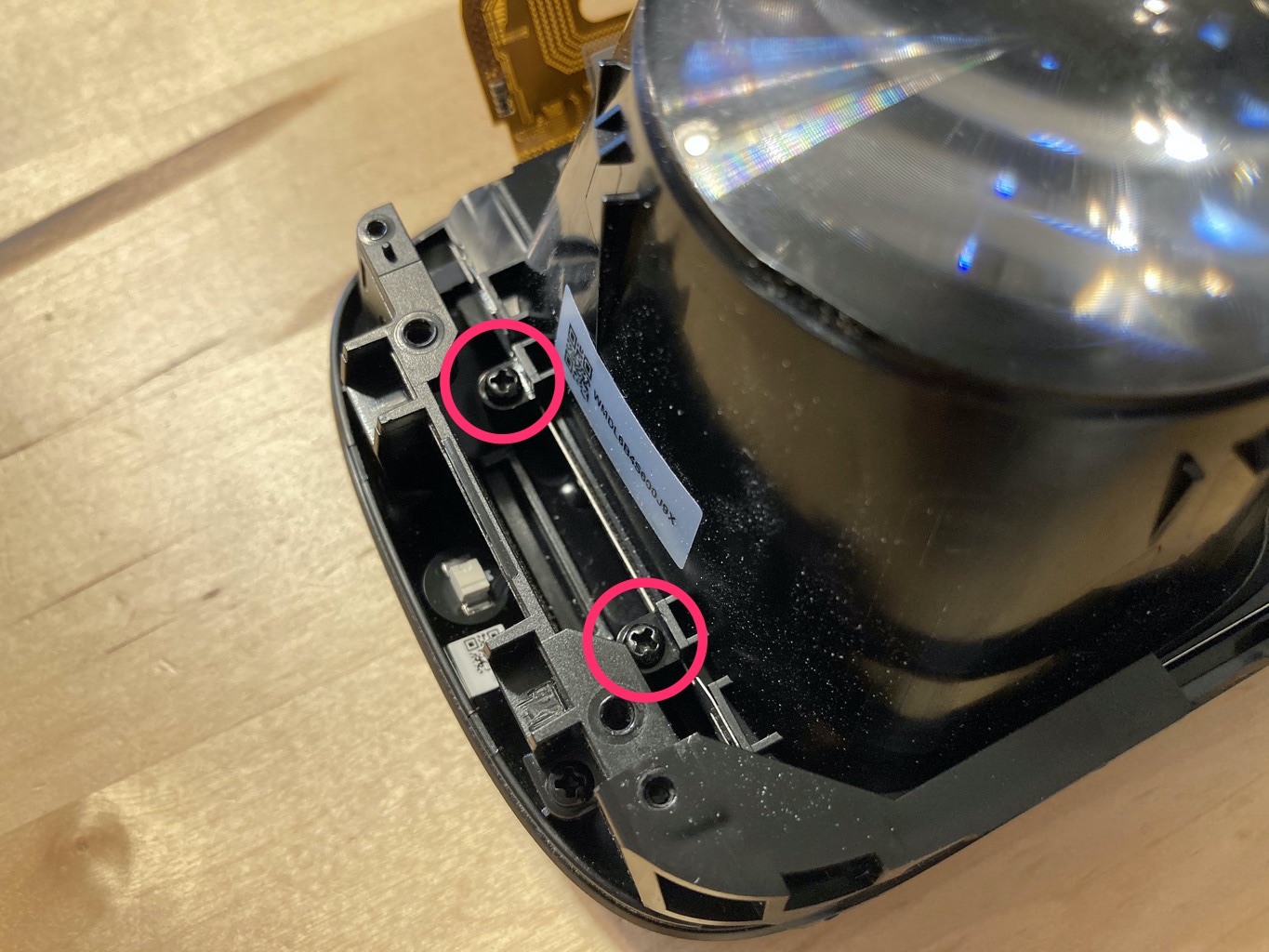
The following image shows the location of 2x T4 screws, 2x small Phillips head screws and 4x large Phillips head screws. Note that there are two pairs of screws that are very close to each other. Remove all eight of these.
There are two more screws here that are not obvious to find. The easier of the two is another 1x small Phillips head screw hiding under the sliding lenses. Hold the lenses apart with your free hand if necessary2 and take it out.
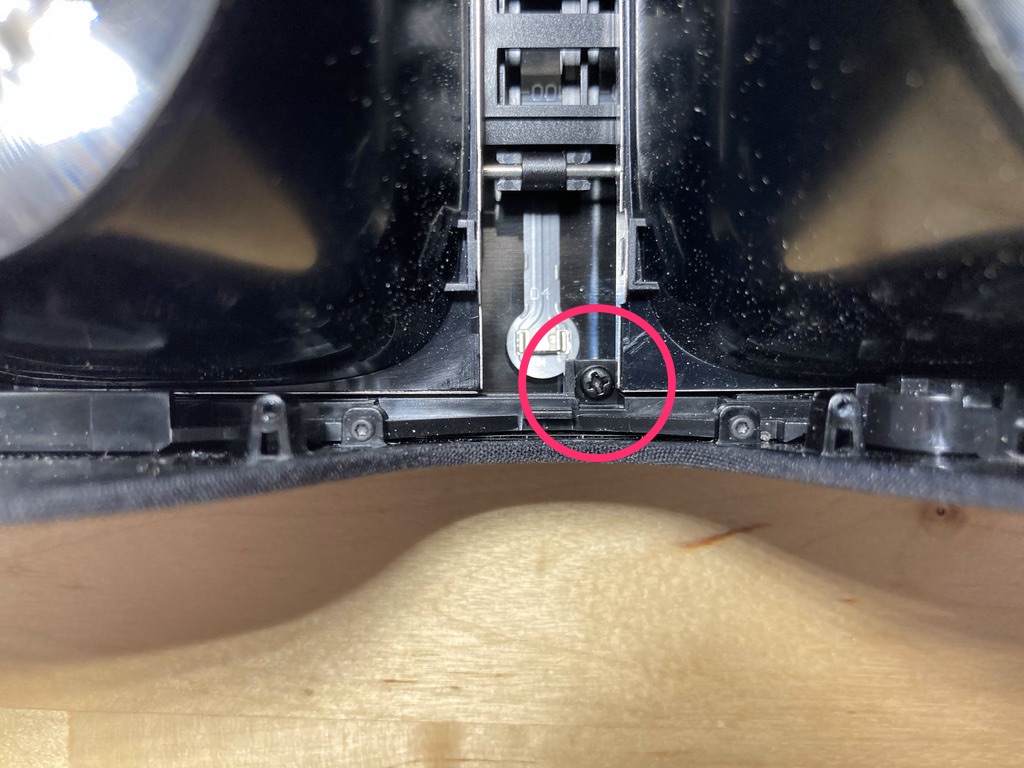
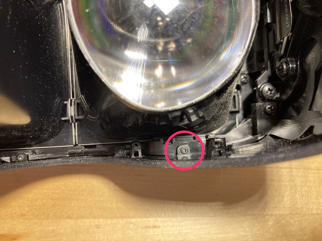
There is also 1x Phillips head shoulder screw tucked away such that it is only accessible using a narrow-shaft Phillips head crossing right over the main board support. This is why replaceable-bit screwdrivers don’t cut it!
Once all the screws are out, it’s time to separate the outer housing from the front of the headset.
Take It Slow!
The outer housing is connected to the front of the headset by several small ribbon cables. Don't rush this part.
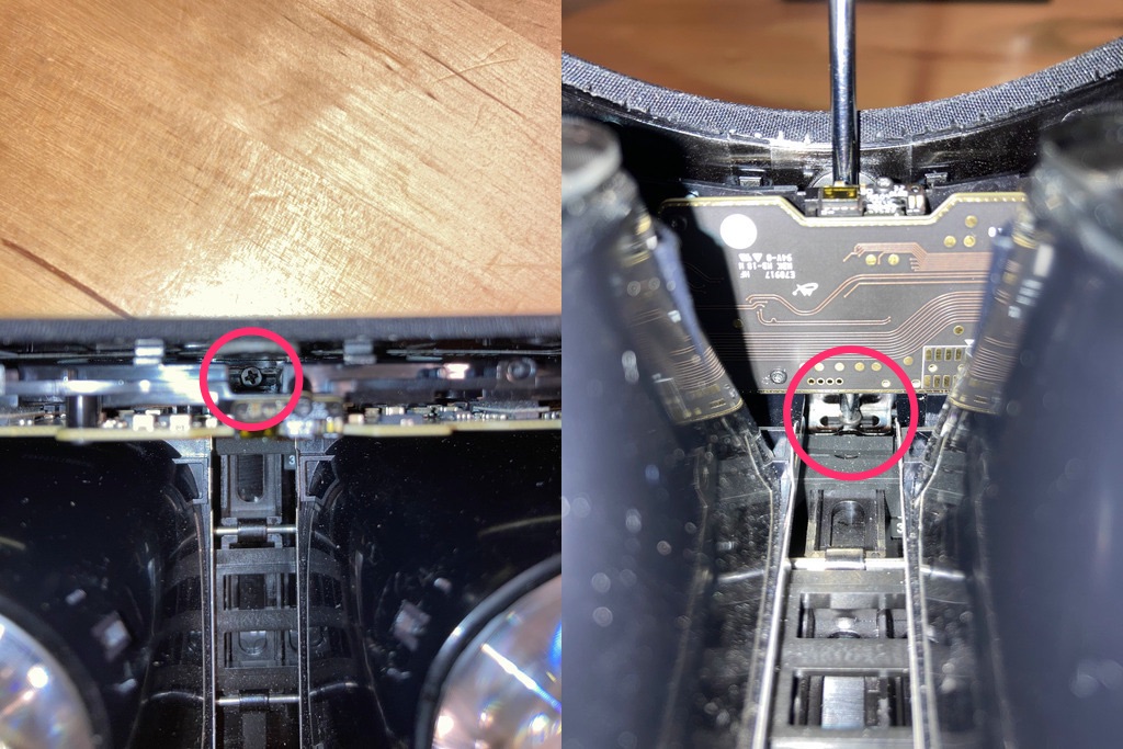
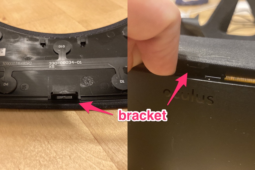
To initially separate the outer housing, bend the top middle of the housing up about 3/16” to allow the bracket that was holding the shoulder screw to clear the main board support. The following picture shows a later view from the inside (left) and what you’ll actually be looking at (right).
While still holding the bracket out of the way, pull the front of the headset straight out from the outer housing until you’ve got a 1/4-1/2” gap between the two. Don’t pull it all the way! There are ribbon cables connecting the outer housing to the rest of the headset.
Lay the headset’s top flat on the work surface. Turn its right side towards you, where you will see a small metal ribbon cable brace. Remove the 2x T4 screws holding the brace in place and take the brace off to expose the ribbon cable connectors.
Lastly, pop the ribbon cable connectors off by sticking your fingernail under their edges and giving them a little tug. They should come off with very little force and a satisfying pop. I don’t suggest using a screwdriver for this step.
Now the outer housing should be free, so put it aside.
5. Main Board
Once the outer housing is separated, you have a lot more room to work.
First, release the breakout board by taking out the 2x T4 screws and popping off the last ribbon cable connector (if you haven’t already).
The breakout board will flop around a bit for the rest of this step, so be careful. I’ve found that removing it first is ultimately easier and less dangerous to the boards.
Don't Break Your Headset!
The next step is by far the riskiest when it comes to breaking your headset unintentionally.
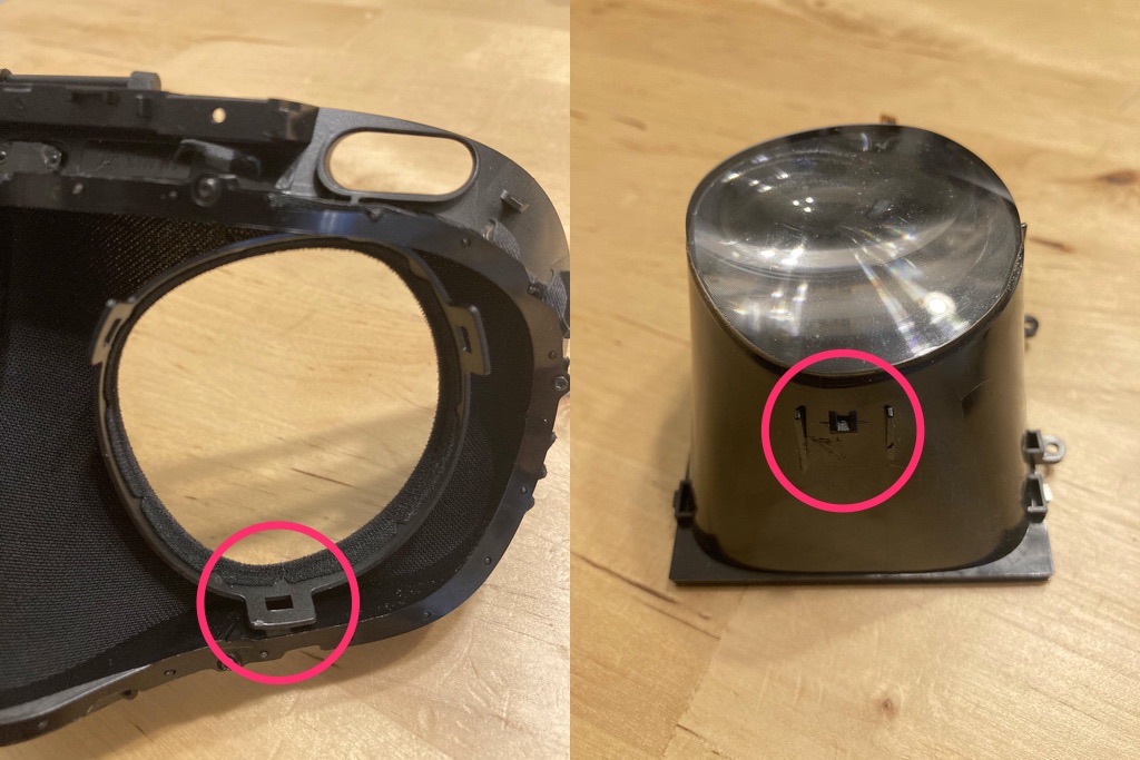
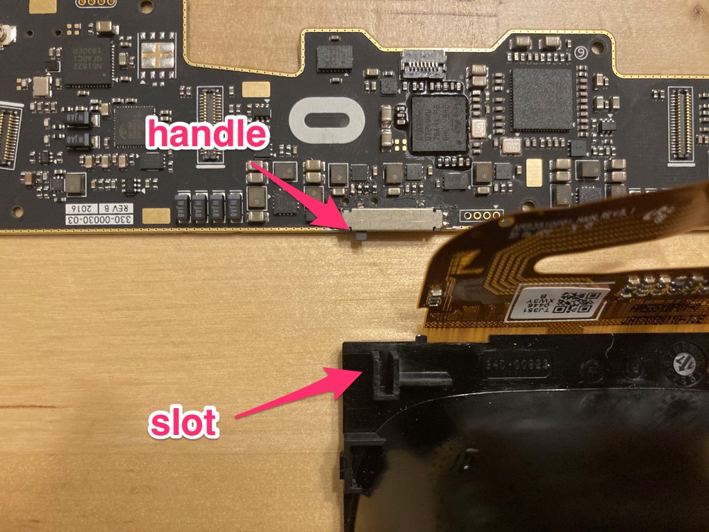
Once the breakout board is free, you’ll want to separate the main board and the main board support. The board and its support have a tendency to flop around too once their screws are removed, so be very careful, because there is a tiny plastic handle on the IPD sensor attached to the board that lodges into a slot on the right lens housing. It is very easy to snap the handle off and permanently break your IPD sensor.3 Also, there are more ribbon cables tethering the main board to rest of the headset that you have to be careful not to break.
The following picture shows the IPD sensor handle and the slot on the right lens housing after the parts have been separated.
First, make sure the lenses are as close to each other as possible. This is the resting position for the lens mount, so moving the lenses first will prevent any abrupt sliding that could break the IPD sensor.
Note that there are two plastic pegs that help align the main board support with the front of the headset.
Hold the main board and its support in place with one hand, relying on the pegs for stability. Don’t let it jostle around or you risk breaking the switch handle! Then, remove the 2x small Phillips head screws holding it in place.
Once the screws are removed, carefully move the main board and its support straight up a little bit and then tilt it away from the headset. It’s attached by two large ribbon cables that you can’t yet remove.
6. Main Board (again) and Other PCBs
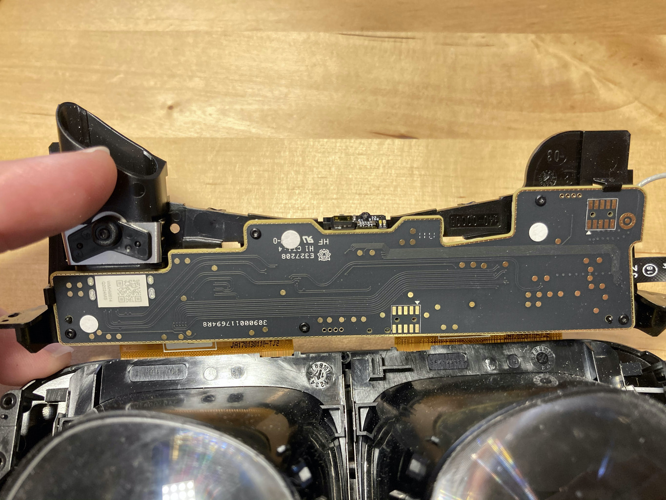
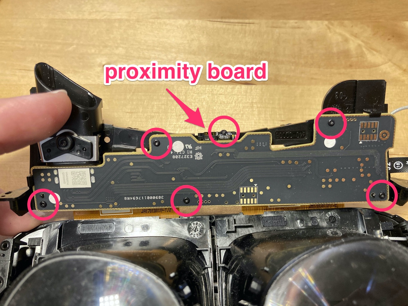
The main board is attached to the plastic main board support by 5x T4 screws and some plastic clips and pegs. The proximity board is attached to the main board by a ribbon cable and the main board support by 1x T4 screw. Remove all six screws. The proximity board will flop a bit, but it’s only twice the size of its own ribbon cable so it won’t move very far or fast.
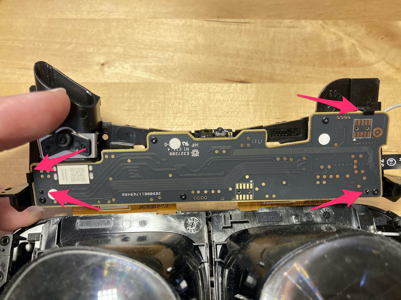
Once all the screws have been removed, carefully tilt and maneuver the main board out of its plastic clips and pegs. There is one of each on each end of the board, which you can see in the following picture. I suggest you release the right side of the board first.
Once the main board is no longer attached to its support, pull it out slightly to expose the ribbon cable connectors.
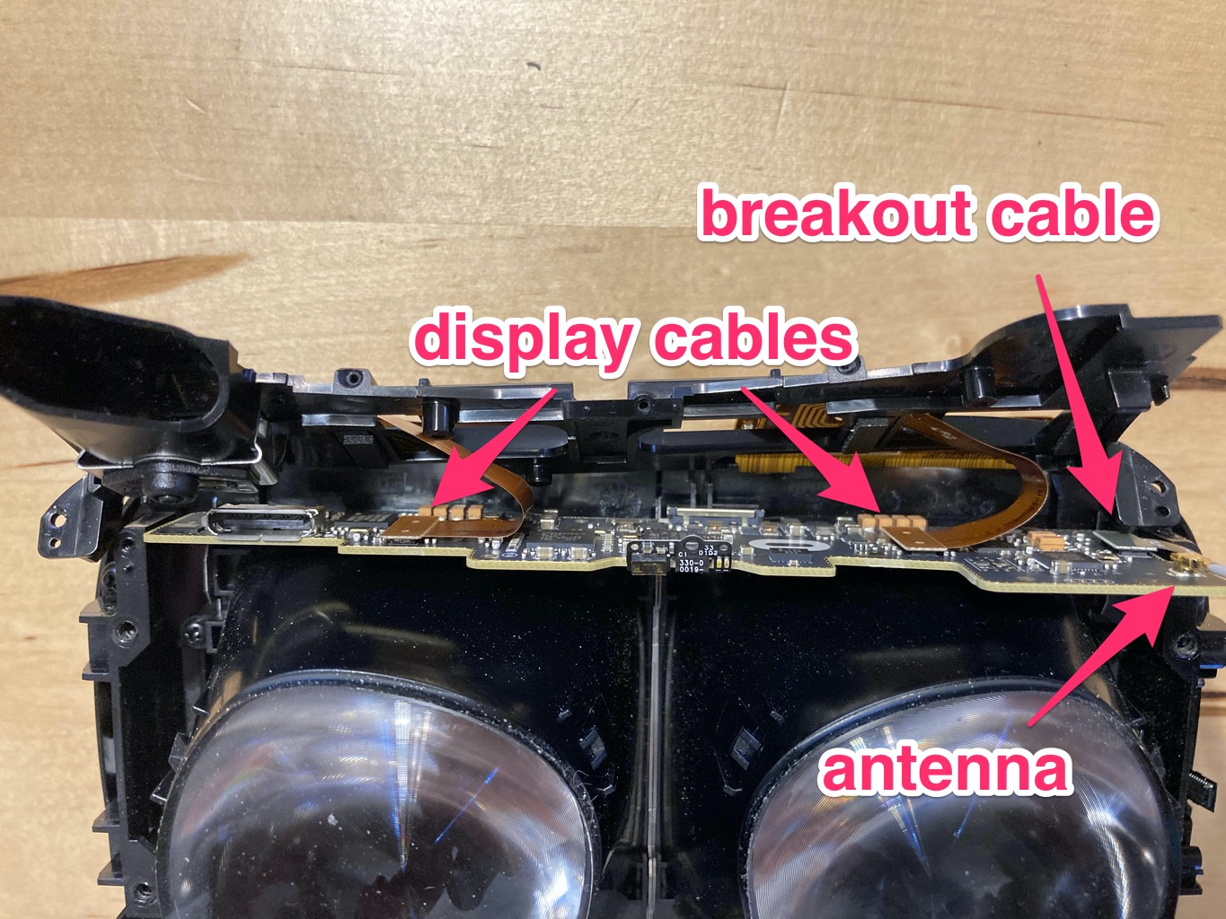
Pop off all the connectors on the main board with your fingernails: two large ribbon cables connected to the display, one small ribbon cable going to the breakout board, and the gold-plated antenna connector on the right side.4
Put the PCBs aside, and unthread the ribbon cables from the main board support.
A note on reassembly: take note of the way that the ribbon cables pass through the support. If you don’t match it, you risk pinching/breaking the cables or even causing the displays to get caught when adjusting the IPD.5
7. Lens Assemblies
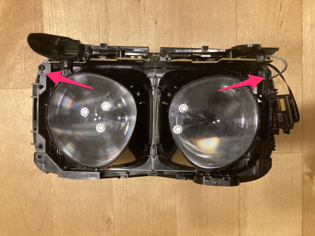
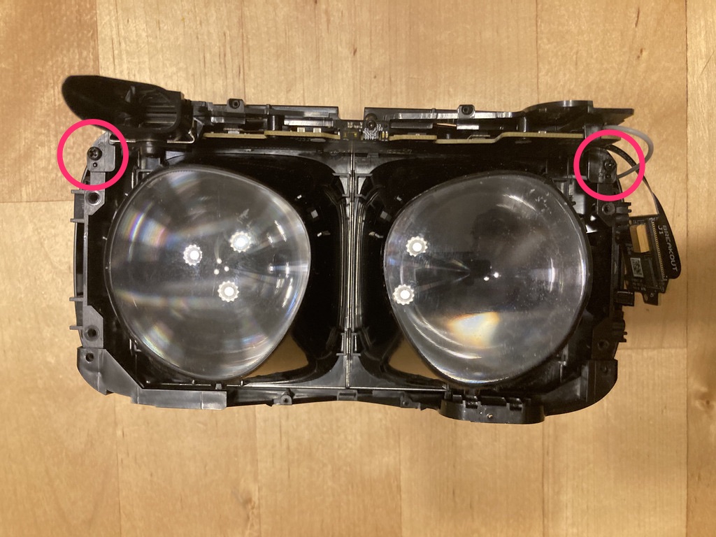
The final step is to separate the lens assemblies from the front of the headset. There are 4x small Phillips head screws holding the displays in, two on each side. Remove all four screws.
The lens assemblies are also held in by four metal clips each, one in each corner. Pry the clips away with your fingernails, starting with the ones in the middle, while lifting the assembly slightly away from the front of the headet. The lens assemblies should pop right out.
8. Wrap-up
…and here you have it, the fully-disassembled CV1!
As usual for teardowns, reassembly is just following the instructions in reverse.
That’s all, folks! I hope you found this interesting and/or helpful. If you’re curious, I used Skitch to annotate some of the images.
Some Thoughts on Repairs
While I was at first put off by the difficulty of removing the shroud, the CV1 is actually quite repairable. The real difficulty lies in finding replacement parts, since it’s discontinued.
I had surprisingly good luck buying headsets and parts off of eBay. There were a number of broken headsets that just had a single display that wasn’t working that you could get for a pretty low price. There were also a handful of sellers with individual parts – boards, mostly – that were more hit-and-miss. I once blindly bought a main board that turned out to have a broken HDMI connector and/or chip, but within minutes of finding that out I had ripped off the entire IPD sensor (not just the plastic handle – all of it) so I didn’t bother to try to return it. Oops. Still, three out of four sales were exactly as broken as advertised.
As for my own headset, the issue turned out to be a faulty main board. Twisting or bending the board slightly causes it to lose power, so I guess that when I swing my head around too fast the acceleration of the board against the headset body causes it to bend ever so slightly and drop out. Very, very annoying, and really destroys the immersion even in a relatively low-immersion game like Beat Saber.
-
Also, I don’t like guides in video form because they’re a pain in the ass to navigate. That’s why this one is pictures! ↩
-
In earlier teardowns I tried to remove this screw before the IPD slider, which you can do, but I found it was easier to keep track of what I was doing if I didn’t split the outer housing screws across two chunks of work. ↩
-
Trust me, I did it twice. ↩
-
As far as I can tell, the Touch controllers use Bluetooth to talk to the headset, and the headset forwards control inputs over USB to the computer. I found this out by accident: I was testing a mostly-disassembled headset by plugging just the displays into the board without any housing or anything else, and had a hell of a time getting the controllers to sync. As soon as I plugged the antenna back in, all my problems were solved. Some futher investigation revealed a Bluetooth chip on the main board, and my computer doesn’t have Bluetooth, so there you have it. ↩
-
These ribbon cables are covered in little obstructive components and are surprisingly tough. I once put one in improperly and it would cause the display to catch and then suddenly snap into position when adjusting the IPD. ↩